
Most water softener installations include a crucial component that often confuses first-time DIYers: the bypass valve. This simple three-valve system controls whether household water flows through the softener or around it, and misunderstanding its operation can lead to wasted salt, inadequate softening, or even damage during maintenance. The bypass valve diagram serves as the roadmap for proper installation, routine operation, and troubleshooting. Whether setting up a new unit, performing maintenance, or diagnosing pressure issues, understanding how to read and interpret a water softener bypass diagram makes the difference between a smooth project and a flooded utility room.
Table of Contents
ToggleKey Takeaways
- A water softener bypass valve diagram is essential for proper installation, maintenance, and troubleshooting—it maps the three-valve system that controls whether water flows through the softener or around it.
- The bypass valve diagram clearly shows inlet, outlet, and bypass port locations along with handle positions for service mode (softened water) and bypass mode (hard water detour), making correct orientation critical during setup.
- Understanding your water softener bypass valve diagram prevents common installation mistakes like reversed inlet/outlet connections, missing O-rings, and incorrect threading that can lead to leaks or failed softening.
- Switch to bypass mode when adding salt, changing filters, replacing resin, or during extended absences—the diagram shows the exact handle positions or valve rotations needed for each scenario.
- When troubleshooting bypass valve issues, consult the diagram to identify whether problems stem from incorrect positioning, mineral deposits, missing gaskets, or the need for professional replacement rather than DIY repair.
What Is a Water Softener Bypass Valve and Why It Matters
A bypass valve is a plumbing mechanism that allows water to detour around the water softener tank and resin bed. It’s typically a three-valve assembly (two shut-off valves and one bypass valve) or a single integrated unit that controls flow direction with a single handle.
The bypass valve serves several essential functions:
- Maintenance access: Isolates the softener from household water supply during filter changes, resin replacement, or system repairs without shutting down the entire home’s water.
- Emergency operation: Provides hard water to the home if the softener malfunctions or runs out of salt at an inconvenient time.
- Initial installation: Allows plumbers to connect the softener to the water line before the unit is ready to operate.
- Seasonal use: Homeowners with vacation properties or seasonal water quality issues can deactivate softening when it’s not needed.
Without a properly functioning bypass, the entire water supply must be shut off to service the softener, an inconvenience that turns a 20-minute salt refill into an all-day disruption. Most building codes don’t specifically mandate bypass valves, but manufacturers include them as standard equipment, and any competent installer will refuse to omit one.
Bypass valves typically use 3/4-inch or 1-inch NPT threaded ports to match standard softener connections. The valve body is usually constructed from brass, PVC, or reinforced polymer, with brass being the most durable option for long-term installations.
Understanding the Bypass Valve Diagram: Key Components Explained
A water softener bypass diagram illustrates the valve assembly, port locations, and flow paths. Reading one correctly requires identifying a few key elements that appear in virtually every configuration.
Inlet and Outlet Ports
The diagram typically shows three main ports:
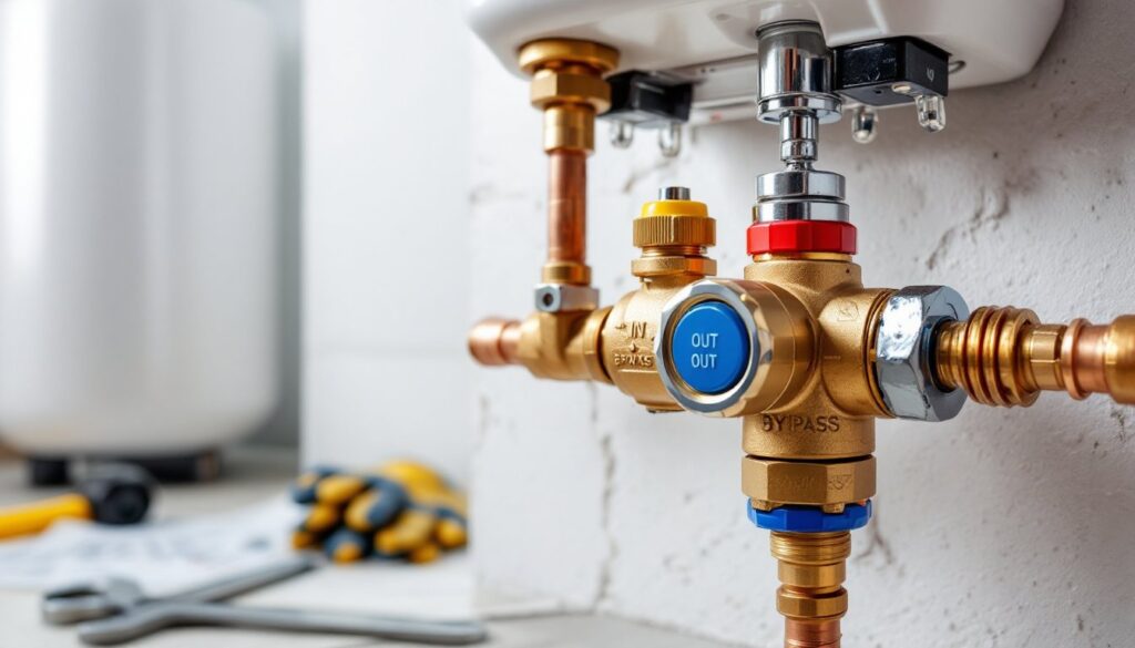
- Inlet port: Where hard water enters from the main supply line. Usually labeled “IN” or marked with an arrow indicating flow direction.
- Outlet port: Where softened water exits back to the household plumbing. Labeled “OUT” or shown with an outbound arrow.
- Bypass port: The third connection that creates the detour route when the valve is in bypass mode.
Most diagrams use color coding, blue for incoming hard water, red or green for outgoing soft water, and sometimes yellow or gray for bypass flow. The physical valve body often includes embossed arrows or raised lettering that corresponds to the diagram, making field identification easier during installation.
Port orientation matters. Single-handle bypass valves (like the popular Fleck and Pentair models) position all three ports along the same plane with standardized spacing (typically 7 to 9 inches center-to-center for the inlet and outlet). Three-valve assemblies arrange the valves in a triangular or linear pattern, with the bypass valve positioned between the two shut-offs.
Valve Handle Positions and Flow Direction
The diagram’s most critical information shows handle or lever positions for each operating mode:
- Service position: Handle pushed in, turned perpendicular to pipes, or aligned with specific arrows (varies by manufacturer). Water flows through the softener, inlet to tank, through resin, then to outlet.
- Bypass position: Handle pulled out, turned parallel to bypass pipe, or rotated 90 degrees from service. Water flows directly from inlet to outlet, skipping the softener entirely.
Some diagrams include a third regeneration position for systems that require manual initiation of the cleaning cycle, though most modern softeners handle this automatically. The key is that water continues flowing to the house during regeneration, it’s just temporarily hard.
Flow direction indicators (arrows) on the diagram should match the physical arrows molded into the valve body. If they don’t align during installation, the valve is either backward or the wrong model for the softener.
How to Read and Use Your Bypass Valve Diagram During Installation
The bypass valve diagram becomes a critical reference during installation, particularly when connecting the valve assembly to both the softener and household plumbing.
Before starting, verify that the diagram matches the actual hardware. Some softeners ship with generic diagrams that don’t reflect the specific valve model included. Check the valve body for a model number and cross-reference it with the manual.
Installation steps using the diagram:
-
Orient the valve assembly: Hold the valve next to the softener head and match the inlet/outlet ports to the corresponding connections on the tank. The diagram shows which port connects to which softener fitting, mixing them up results in backward flow and no softening.
-
Identify supply line connections: The diagram indicates which side connects to the incoming main water line. Most diagrams show this as the left side when facing the unit, but confirm with the labeled arrows.
-
Check for O-rings and washers: Diagrams often include exploded views showing gaskets, O-rings, or fiber washers at each connection point. These aren’t optional, missing a single O-ring causes leaks that won’t appear until the system pressurizes.
-
Thread direction and torque: While diagrams don’t usually specify torque values, they do show thread types. NPT threads require Teflon tape or pipe dope: compression fittings do not. Over-tightening plastic valve bodies (common on budget models) can crack the housing, hand-tight plus a quarter turn with a wrench is typically sufficient.
-
Verify bypass position during testing: Before connecting the softener to the water line, set the valve to bypass (as shown in the diagram). This allows the installer to pressurize the household plumbing, check for leaks at the valve connections, and ensure water flows to the home before introducing the softener into the system.
Pro tip: Take a photo of the diagram with a smartphone and keep it saved. The printed manual often gets tossed or buried in a drawer, and you’ll want that reference during the first maintenance cycle.
Operating Your Bypass Valve: When and How to Switch Modes
Knowing when to engage the bypass is as important as knowing how. The diagram shows the mechanical positions: experience teaches the practical scenarios.
When to switch to bypass mode:
- Adding salt: Not strictly necessary, but switching to bypass during salt refills prevents accidental overfilling into the brine tank vent, which can occur if regeneration triggers mid-fill.
- Changing filters: If the softener includes pre- or post-filters, bypass mode drops system pressure and prevents water hammer when unscrewing filter housings.
- Resin replacement: Essential. Resin bed service requires opening the tank, which is impossible under pressure.
- Vacation or extended absence: Prevents stagnant water from sitting in the resin bed, which can harbor bacteria or allow iron buildup.
- Plumbing repairs downstream: Isolates the softener so it doesn’t drain when working on fixtures supplied by the softened water line.
- Testing hard water appliances: Some appliances (like certain tankless water heaters or evaporative coolers) perform better with hard water. Bypass mode allows testing without full system changes.
How to switch (per typical diagram instructions):
-
Single-handle models: Pull the handle straight out (bypass) or push straight in (service). Some models require a quarter-turn after pulling. The diagram will show a side-view illustration indicating handle extension.
-
Three-valve models: Close both the inlet and outlet valves (perpendicular to pipes), then open the center bypass valve (parallel to bypass pipe). The diagram shows all three positions simultaneously, which looks confusing but simply means “close these two, open this one.”
-
Confirm the switch: Open a cold tap. In bypass mode, water pressure should remain normal but hardness increases (test with soap, hard water doesn’t lather well). In service mode, water should feel slicker and soap should lather easily.
Safety note: Never force a stuck valve handle. Corrosion or mineral buildup can freeze the mechanism. Apply penetrating oil, wait 15 minutes, then try again with steady pressure. Forcing it can snap the handle or crack the valve body, turning a maintenance task into a replacement project.
Troubleshooting Common Bypass Valve Issues Using the Diagram
When problems arise, the bypass valve diagram helps pinpoint whether the issue is with the valve itself, the softener, or the installation.
No water flow in service mode:
Check the diagram’s flow path. If water doesn’t reach the house when the valve is in service position, either the inlet or outlet valve is closed (on three-valve systems) or the handle isn’t fully seated (on single-handle units). The diagram shows the correct handle depth or valve orientation, compare the physical setup to the illustration.
Water flows but remains hard:
The bypass valve may be partially engaged. Consult the diagram for the exact service position. Some valves have a “middle” position that splits flow between bypass and service, reducing softener effectiveness. Push or turn the handle to the fully engaged position as shown.
Leaking at valve connections:
Refer to the exploded diagram view (if included) to identify which O-ring or gasket is failing. Leaks at the valve-to-softener connection usually indicate a missing or damaged tank O-ring (commonly a thick black rubber ring). Leaks at the valve-to-pipe connection suggest inadequate Teflon tape or cross-threading.
Valve won’t switch positions:
Mineral deposits often lock up bypass valves in hard water areas. The diagram can help identify if the valve design includes a removable cartridge or if the entire assembly requires replacement. Some diagrams show disassembly steps, if yours does, the valve is serviceable. If not, replacement is usually the only option.
Backwards installation:
If the softener never worked correctly from day one, compare the actual installation to the diagram. Reversed inlet/outlet connections cause constant bypass, water enters the outlet port, hits a dead end or weak flow path, and exits through the inlet, never touching the resin. The diagram’s arrows should match the embossed arrows on the valve body and the flow direction of your supply line.
When to call a professional: If the diagram shows internal components like springs, pistons, or diaphragms, and the valve is leaking from the body (not the connections), replacement is likely necessary. While some experienced DIYers rebuild valve assemblies, most find that labor costs approach or exceed the price of a new valve ($30–$80 for standard units). If the softener is still under warranty, contact the manufacturer before attempting repairs, valve disassembly often voids coverage.